
How to Read a Lawn Sprinkler System Wiring Diagram
A lawn sprinkler system wiring diagram shows how a 24-volt controller sends power to each irrigation valve. In the most common setup, one white common wire connects to every valve solenoid, while one separate color-coded zone wire runs from each controller station terminal to its matching valve.
| Diagram part | What it does |
|---|---|
| Controller terminals | Send 24VAC power when a zone is scheduled to run |
| C or COM terminal | Connects the shared common wire |
| Zone terminals 1, 2, 3, etc. | Connect to individual zone wires and valve solenoids |
| Valve solenoid | Opens the irrigation valve when its zone receives power |
| Waterproof wire connectors | Protect underground splices from moisture and corrosion |
Most residential systems use 16- or 18-gauge direct-burial, multi-conductor wire. The key is simple: each valve needs the shared common wire plus its own dedicated station wire. Because standard 24VAC solenoids are not polarized, either solenoid lead can serve as the common-side connection.
A clear wiring diagram helps property managers and owners trace dead zones, plan repairs, and avoid costly mistakes such as loose splices, undersized wire, or a pump wired directly to a controller terminal. The sections ahead explain the layout, color conventions, valve connections, sensors, relays, and safe underground routing.
I am Troy Basmajian, President of Southern California Tree & Landscape, where I help oversee irrigation work for residential, commercial, HOA, municipal, and institutional properties throughout Southern California. My experience with lawn sprinkler system wiring diagram planning and irrigation system service informs the practical guidance in this guide.
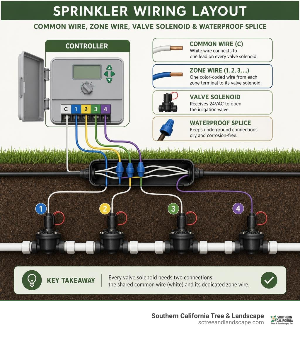
Core Components and Wire Color Coding in a Lawn Sprinkler System Wiring Diagram
To build a reliable automatic irrigation system, you need to understand how low-voltage power moves from the wall outlet to your yard. Standard residential sprinkler controllers operate on safe, 24-volt alternating current (24VAC). A plug-in transformer steps down your home’s 120-volt household current to 24VAC before it reaches the controller terminal block.
When reviewing a lawn sprinkler system wiring diagram, you will find several key electrical components working together:
- The Irrigation Controller (Timer): The brain of your system. It houses terminal blocks labeled for power inputs, common wires (
CorCOM), individual stations or zones (1,2,3, etc.), and special outputs like Master Valve/Pump (P/MV) or Sensors (S1,S2). - Direct-Burial Multi-Conductor Cable: A heavy-duty jacketed cable containing multiple color-coded insulated copper wires designed to withstand soil exposure, moisture, and temperature fluctuations.
- Automatic Valve Solenoids: Electromagnets attached to each hydraulic irrigation valve. When a 24VAC current passes through the coil, it lifts an internal plunger, allowing water pressure to open the valve and supply water to that zone’s sprinkler heads.
- Waterproof Wire Connectors: Essential silicone- or gel-filled wire nuts that seal electrical splices inside valve boxes, shielding connections against subterranean moisture and root intrusion.
When factoring in The Ballpark Cost of a New Sprinkler System: Don’t Get Soaked by Hidden Fees, selecting high-quality direct burial wire and weather-proof connectors right from the start pays off by preventing costly ground faults later.
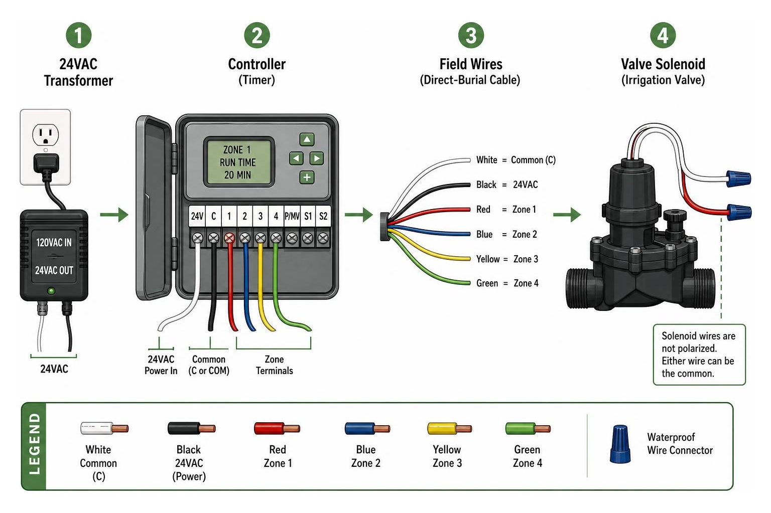
Standard Wire Colors in a Lawn Sprinkler System Wiring Diagram
While high-voltage AC wiring in residential housing follows strict national electrical codes, low-voltage irrigation systems rely on strong industry conventions rather than rigid laws. Following standard wire color codes simplifies installation and makes future troubleshooting painless.
The fundamental rule in sprinkler wiring is that white is always reserved for the common wire. The common wire acts as the shared neutral return pathway for all valve solenoids back to the controller’s C terminal.
For the individual station (zone) wires, professionals use distinct colors for each numerical station output. A universally recognized color order for an 8-station setup includes:
- Common Wire: White (shared by all valves)
- Station 1: Brown
- Station 2: Red
- Station 3: Orange
- Station 4: Yellow
- Station 5: Green
- Station 6: Blue
- Station 7: Violet (or Purple)
- Station 8: Gray
If you are running multi-strand wire bundles across large landscapes, we strongly recommend purchasing multi-conductor cable with at least two extra “spare” conductors beyond your current zone count. For example, if you have a 6-zone system, install an 8-conductor or 10-conductor cable. These extra unused strands serve as backup wires if a underground conductor breaks or if you decide to add landscape zones later.
Wire Gauge Selection and Distance Limits
Choosing the correct wire thickness (measured by American Wire Gauge, or AWG) ensures that adequate voltage reaches your valve solenoids without excessive voltage drop over long cable distances. If the voltage drops too low, solenoids will chatter, overheat, or fail to open completely.
Solid single-strand copper wire (such as 18 AWG or 16 AWG) is standard for residential systems. For multi-valve manifolds situated close together, standard 18 AWG multi-strand wire provides a flexible, cost-effective wiring solution. For longer runs across sprawling properties in Covina, Torrance, or South Bay CA, stepping up to 16 AWG or 14 AWG wire prevents voltage drop.
The maximum allowable distance between an irrigation controller and a valve solenoid depends on the combined gauge of both the common wire and the specific zone wire:
| Common Wire Gauge | Zone Wire Gauge | Maximum Run Distance (Feet) |
|---|---|---|
| 18 AWG | 18 AWG | 850 ft |
| 18 AWG | 14 AWG | 1,210 ft |
| 16 AWG | 14 AWG | 1,650 ft |
| 14 AWG | 14 AWG | 2,150 ft |
How to Connect Valve Solenoids and Manifolds
Once your multi-strand wire bundle is pulled from the timer location to your outdoor valve boxes, you are ready to make physical connections at the valve manifold.
Every standard 24VAC valve solenoid has two lead wires extending out of its top housing. Because alternating current alternates polarity 60 times per second (60 Hz), solenoid lead wires do not have electrical polarity. It does not matter which lead wire you choose for the common wire and which lead you choose for the hot zone wire.
To wire a single valve or a multi-valve manifold correctly, consult the official Sprinkler System Installation Guide – Rain Bird and follow this multi-zone sequence:
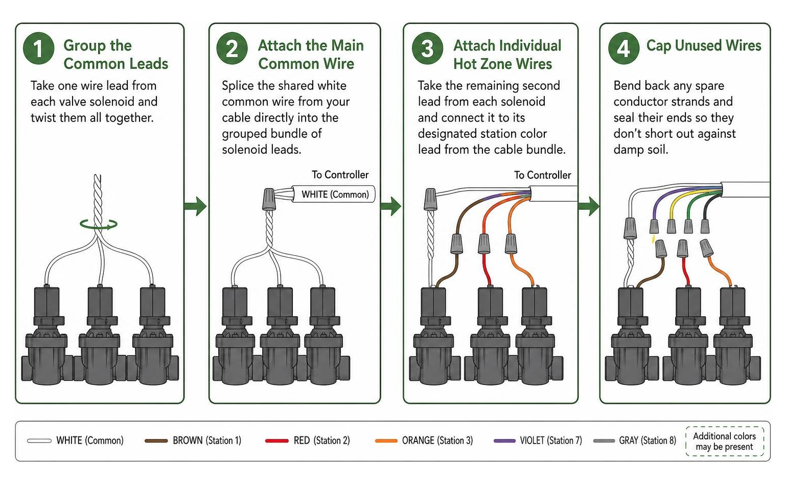
- Group the Common Leads: Take one wire lead from each valve solenoid in the manifold box and twist them all together.
- Attach the Main Common Wire: Splice the shared white common wire from your multi-conductor cable directly into this grouped bundle of solenoid leads.
- Attach Individual Hot Zone Wires: Take the remaining second lead wire from each solenoid and connect it to its designated station color lead from the cable bundle (e.g., Solenoid 1 to Brown, Solenoid 2 to Red, Solenoid 3 to Orange).
- Cap Unused Wires: Bend back any spare conductor strands and seal their ends so they don’t short out against damp soil.
Solenoid Wiring and Using a Lawn Sprinkler System Wiring Diagram
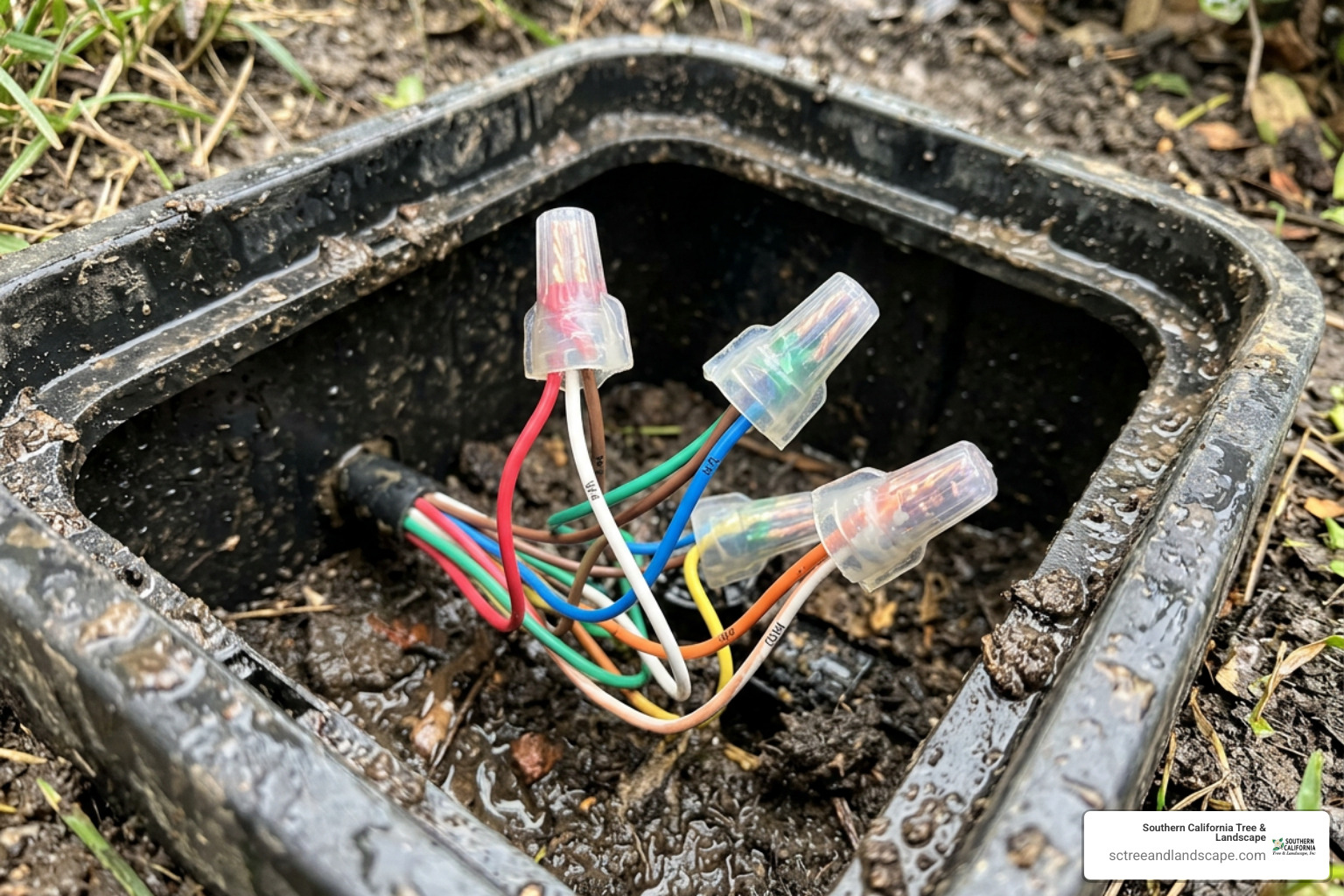
The subterranean environment inside an irrigation valve box is full of moisture, condensation, and mud. Standard household wire nuts or electrical tape will corrode within months, causing intermittent operation or dead zones.
Always use silicone-filled or gel-filled waterproof wire connectors (such as 3M DBR/Y-6 or King Safety wire connectors) for every underground splice. These specialty connectors encapsulate the bare twisted copper wires in a thick dielectric silicone sealant, locking out moisture and oxygen permanently.
If you are experiencing a zone that refuses to turn on, consult our guide on Sprinkler Repair Quick and Easy: A DIY Guide. Often, the culprit is simply a corroded wire splice that requires cutting back to fresh copper and resealing with a fresh waterproof connector.
Wiring Master Valves, Pump Relays, Sensors, and Indexing Valves
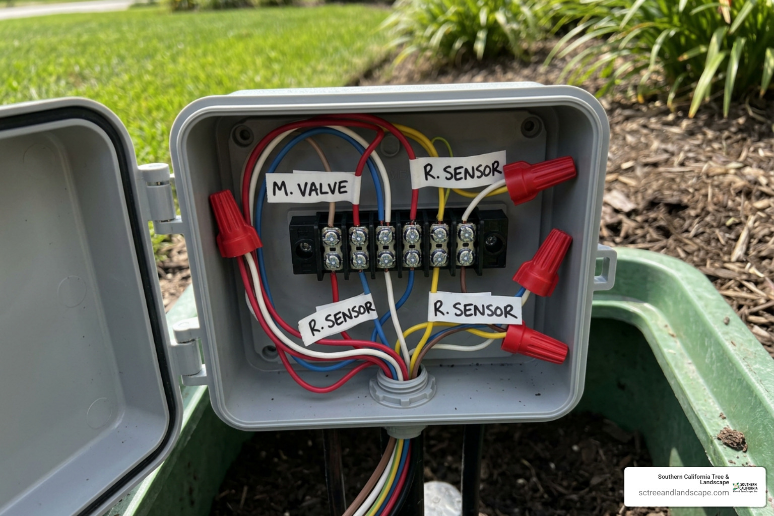
Beyond standard zone valves, advanced automatic systems feature master valves, booster pumps, rain shutoff devices, and weather sensors. Correctly incorporating these devices into your lawn sprinkler system wiring diagram ensures high efficiency and guards against flooding or pump failure.
Master Valve and Pump Start Relay Setup
A Master Valve is a normally closed electric valve installed at the point of connection where your irrigation system branches off the main water line. It opens only when the controller signals any zone to start watering.
To wire a Master Valve:
- Connect one lead from the master valve solenoid to the controller terminal labeled
P/MV(Pump/Master Valve). - Connect the second lead of the master valve solenoid to the main white common wire (
C) along with the rest of your zone valves.
If your system draws water from a well, pond, or booster pump rather than pressurized municipal water, you must use a Pump Start Relay. Because irrigation controllers output low-voltage 24VAC power while irrigation pumps run on high-voltage 110V or 220V power, connecting a pump directly to a timer terminal will ruin the controller and void its warranty.
A Pump Start Relay acts as an isolated electrical switch: the controller sends a 24VAC trigger signal to the relay coil, which safely closes the heavy-duty switch contacts to power up the pump.
When wiring master valves and pump relays, keep these critical technical guidelines in mind:
- Distance Rule: Install the Pump Start Relay at least 15 feet away from the sprinkler controller to prevent electromagnetic interference from triggering control board errors.
- Current Draw Threshold: Ensure the total combined electrical draw of the Pump Start Relay coil plus the active valve solenoid does not exceed 1.3 Amps at 24 VAC, 60 Hz.
- App & Timer Setup: Enable the “Master Valve / Pump Enable” option in your controller settings so the timer energizes the
P/MVterminal whenever any station runs.
Connecting Rain Sensors and Specialized Valves
Modern smart controllers rely on rain sensors or soil moisture sensors to interrupt watering during storms. Wired sensors connect directly to dedicated terminal slots labeled S1, S2, or SEN.
- Standard Rain Sensors: Remove the factory jumper clip connecting the two sensor terminals on the controller block, then insert the two wires from the rain sensor into
S1andS2. When rain swells the sensor disks, it breaks the circuit, freezing controller output until the disks dry out. - Indexing Valves: Common in older or specialized properties, indexing valves utilize a single water inlet that mechanically rotates output chambers each time water pressure turns off and on. To run an indexing valve on a modern controller, wire its single solenoid to Station 1. Set a mandatory 5-minute delay between zones in your timer program. This pause allows system line pressure to drop completely to zero so the internal indexing mechanical cam can cycle smoothly to the next chamber.
Best Practices for Trenching, Protecting, and Routing Underground Wire
Even a flawless electrical setup can fail if physical wires are damaged during lawn maintenance, aerating, or planting. Protecting low-voltage cable underground requires careful trenching and placement techniques.
As outlined in the Hunter Residential Sprinkler System Design Guide, all irrigation wires must be buried to a minimum depth of 6 inches. However, standard practice for complete line installations involves digging main supply trenches 10 to 12 inches deep and lateral branch lines 6 to 8 inches deep.
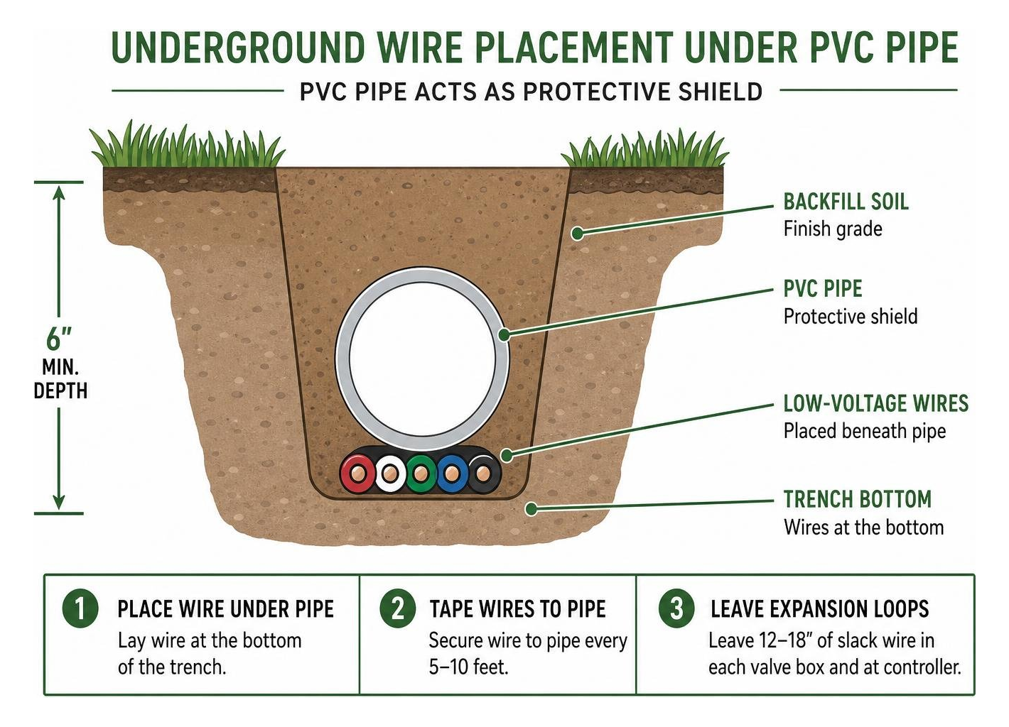
To maximize physical protection for your wire runs, adopt these field-proven installation practices:
- Place Wire Underneath Pipe: Lay your multi-conductor cable at the very bottom of the trench, underneath your schedule 40 PVC or poly irrigation pipe. The rigid pipe acts as a physical shield against shovels, lawn aerators, and edging tools.
- Tape Wires to Piping: Secure the wire bundle to the underside of the PVC pipe every 5 to 10 feet using electrical tape before backfilling the trench. This prevents wire floating and keeps runs neat.
- Leave Expansion Loops: Leave a 12- to 18-inch coiled loop of slack wire inside each valve box and at controller transitions. This extra slack prevents wire strain caused by soil settling and temperature-induced expansion and contraction.
- Protect Vertical Building Runs: Where the multi-strand cable emerges from the soil and ascends an exterior wall to the controller housing, run the wire inside protective PVC conduit or secure it tightly with plastic electrical mounting staples.
Following these practices ensures smooth operation when carrying out an Automatic Sprinkler System Installation.
Frequently Asked Questions about Sprinkler Wiring
Does polarity matter when connecting irrigation solenoid wires?
No, polarity does not matter when wiring standard 24VAC residential irrigation valve solenoids. Alternating current (24VAC) switches electrical direction 60 times per second, so there is no fixed positive or negative lead. You can connect either solenoid wire lead to the shared white common wire and the other lead to your color-coded station wire without affecting performance.
How deep do sprinkler system wires need to be buried?
Sprinkler wiring must be buried at least 6 inches deep according to general low-voltage landscape standards. However, placing wire 10 to 12 inches deep alongside main supply lines beneath PVC piping provides superior protection against aeration tines, shovel strikes, and garden tillers. Always consult local building codes in your municipality before trenching.
What is the difference between wiring common wires in series vs parallel?
Wiring common wires in series (daisy-chaining) means running one continuous white common wire from valve box to valve box, splicing into it at each solenoid stop along a single path. Wiring common wires in parallel means running separate cable bundles with individual common wires from multiple valve boxes back to a central point or directly to the controller terminals.
Electrically, both methods function identically because all common terminals internally link to the same ground plane inside the controller. Daisy-chaining reduces the total amount of copper wire required, while parallel wiring can simplify isolated diagnostic testing.
Conclusion
Understanding a lawn sprinkler system wiring diagram boils down to simple low-voltage circuit fundamentals: a shared white common wire, dedicated color-coded station wires, 24VAC solenoids, and waterproof gel splices. By choosing proper wire gauges, maintaining trench depth minimums, and installing protective relays for pumps, your automatic sprinkler system will deliver years of worry-free landscape health.
If you are dealing with persistent valve failures, broken underground lines, or planning a full landscape overhaul across Torrance, Harbor City, Covina, or the South Bay, let our expert team help.
At Southern California Tree & Landscape, our ISA-certified experts and experienced crews bring family-owned dedication to every job. Explore our Professional Irrigation Services or give us a call today to schedule a comprehensive system diagnostic and repair!